
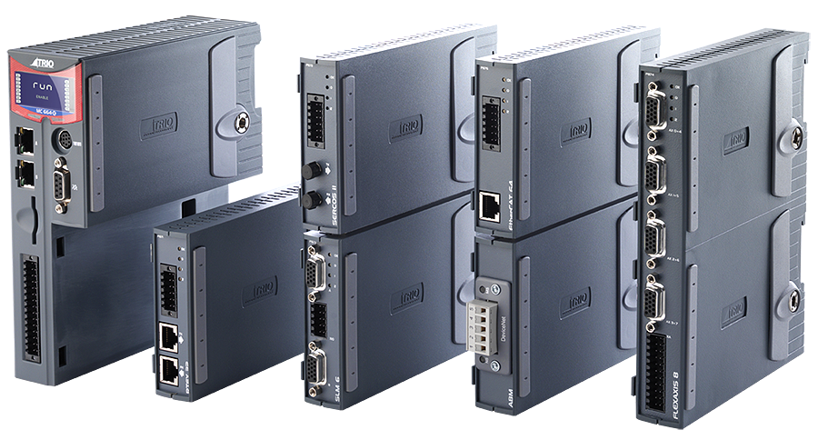
Overview
The MC664 Expansion Module System allows configuration of your system by connecting up to 7 half height or 3 full height modules.
Each module attaches to the controller via a high density bus connection and a uniquely designed screw that integrates with the earth planes of all expansion modules and the controller. Trio's Feature Enable Code system for axis activation allows the whole system to be scaled to your requirements.
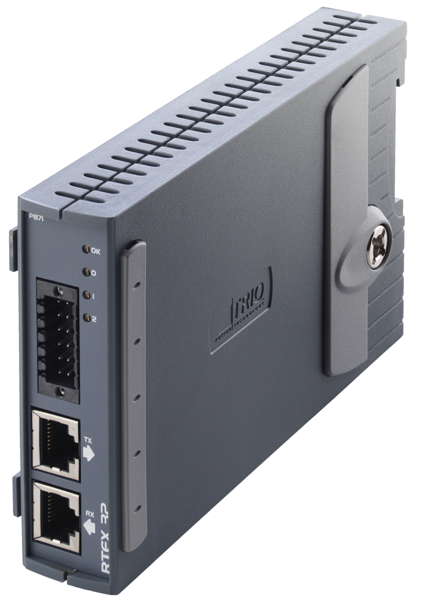
Panasonic RTEX Module
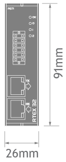
P871
For use with the latest range of Panasonic MINAS A4N and A5N amplifiers supporting the Panasonic Real Time Express (RTEX) network.
Features
- 8 Registration inputs at 100nS per module
- Drive parameters setup from the controller
- Position Set point update 1mS up to 64 axes
- RJ45 Connector
- Ring Topology
- 4 LED status indicators
Allows Plug & Play interconnection with Shielded twisted pair (TIA/EIA-568B CAT5e or more) Ethernet cables. A single interface supports up to 32 axes of Panasonic MINAS A4N and A5N amplifiers. The module comes with 2 axes enabled. Further axes can be enabled with 'Feature Enable Codes'
Installing your system is easy! Simply connect Power, Motor & Feedback to the amplifier using supplied cables. Connect motion control & amplifier using network cable with RJ45 connectors and Power up the system. The MC664 recognises the amplifiers and installs support automatically.
| Network | Ethernet based MINAS A4N / A5N |
| Network Speed | 100Mbps 1msec or 500usec update operation |
| Topology | Ring |
| Max Slaves per Interface Ring | 32 |
| Max Interfaces per MC664 | 7 |
| Max Axes per MC664 | 64 |
| Cable | STP Cat 5-e or Better |
| Bus to MC664 | 32 Bit |
| Registration Inputs | 8 x 24V Inputs + 1 Drive Registration Input / Axis |
| Optically Isolated registration Inputs | Y |
| Map Any I/O to Any Axis | Y |
| Supported Modes | Cyclic Position, Cyclic Speed, Cyclic Torque |
| Axis Feature Enable Codes | P701, P702, P704, P708, P716, P732 |
| UL and CE marked for EMC | |
| RoHs | Compliant |
| Guides | |
|---|---|
| Data Sheet | |
| Quick Start Guide | Simple set up guide |
| Flex Axis Splitter Cable (P381) | Simple Pin-Out guide |
| Manuals | |
|---|---|
| The Technical Reference Manual can be downloaded in full or as separate sections. All in PDF format. | |
| MC664 Expansion Modules (Chapter 3).pdf | |
| Certificates | |
|---|---|
| EC Declaration | |
| UL Listing | Please insert E238097 UL File Number in the search box. |
| CAD Data | |
|---|---|
| Drawings are available in the following formats: DXF, IGES, DWG, STEP and SolidWorks. These files are included in the Zip file below. | |
| Download Zip file | |
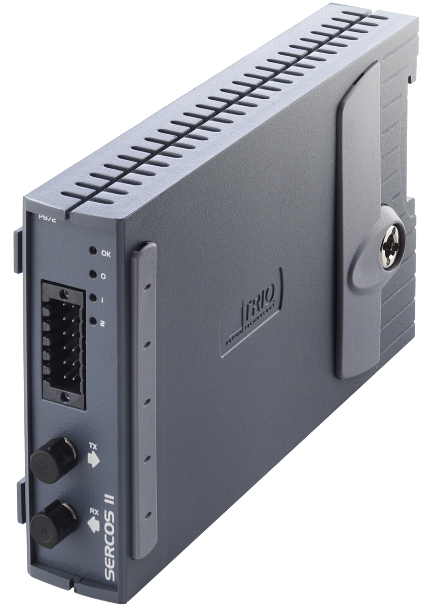
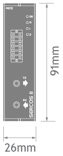
Sercos Module
P872
Trio's sercos support has been designed from the ground up to uniquely fulfil the needs of your customers, and to meet all their automation control requirements.
Features
- Based on Sercon 816 ASIC
- Maximum of 250uS update rate
- 4, 8, 16 MBit/S network speed
- 9mm FSMA Connector
- Ring Topology
- 4 LED Status indicators including RING STATUS
- Each module has 8 registration inputs with 100nsec resolution
- Choice of Drive based or Master based registration
Servo drives from a wide variety of sercos compatible manufacturers can be connected via the fibre-optic ring.
The Motion Coordinator software allows for configuration of the servo drives, reading and writing drive parameters, and running cyclically in speed or position modes. Each module is configured with 2 servo axes. Additional axes can be enabled using “Feature Enable Codes".
Baud rate and light intensity are software configurable, and standard drive profiles can be selected through Motion Perfect.
| Network | sercos |
| Network Speed | 4, 8 or 16Mbps |
| Topology | Ring |
| Max Slaves per Interface Ring | 16 |
| Max Interfaces per MC664 | 7 |
| Max Axes per MC664 | 64 |
| Cable | Fibre-optic |
| Bus to MC664 | 32 Bit |
| Interpolated time based registration | 8 x 24V inputs |
| Remote registration | Y |
| Optically Isolated registration Inputs | Y |
| Map Any I/O to Any Axis | Y |
| Axis Feature Enable Codes | P701, P702, P704, P708, P716, P732 |
| RoHs | Compliant |
| Guides | |
|---|---|
| Data Sheet | |
| Quick Start Guide | Simple set up guide |
| Flex Axis Splitter Cable (P381) | Simple Pin-Out guide |
| Manuals | |
|---|---|
| The Technical Reference Manual can be downloaded in full or as separate sections. All in PDF format. | |
| MC664 Expansion Modules (Chapter 3).pdf | |
| Certificates | |
|---|---|
| UL Listing | Please insert E238097 UL File Number in the search box. |
| CAD Data | |
|---|---|
| Drawings are available in the following formats: DXF, IGES, DWG, STEP and SolidWorks. These files are included in the Zip file below. | |
| Download Zip file | |
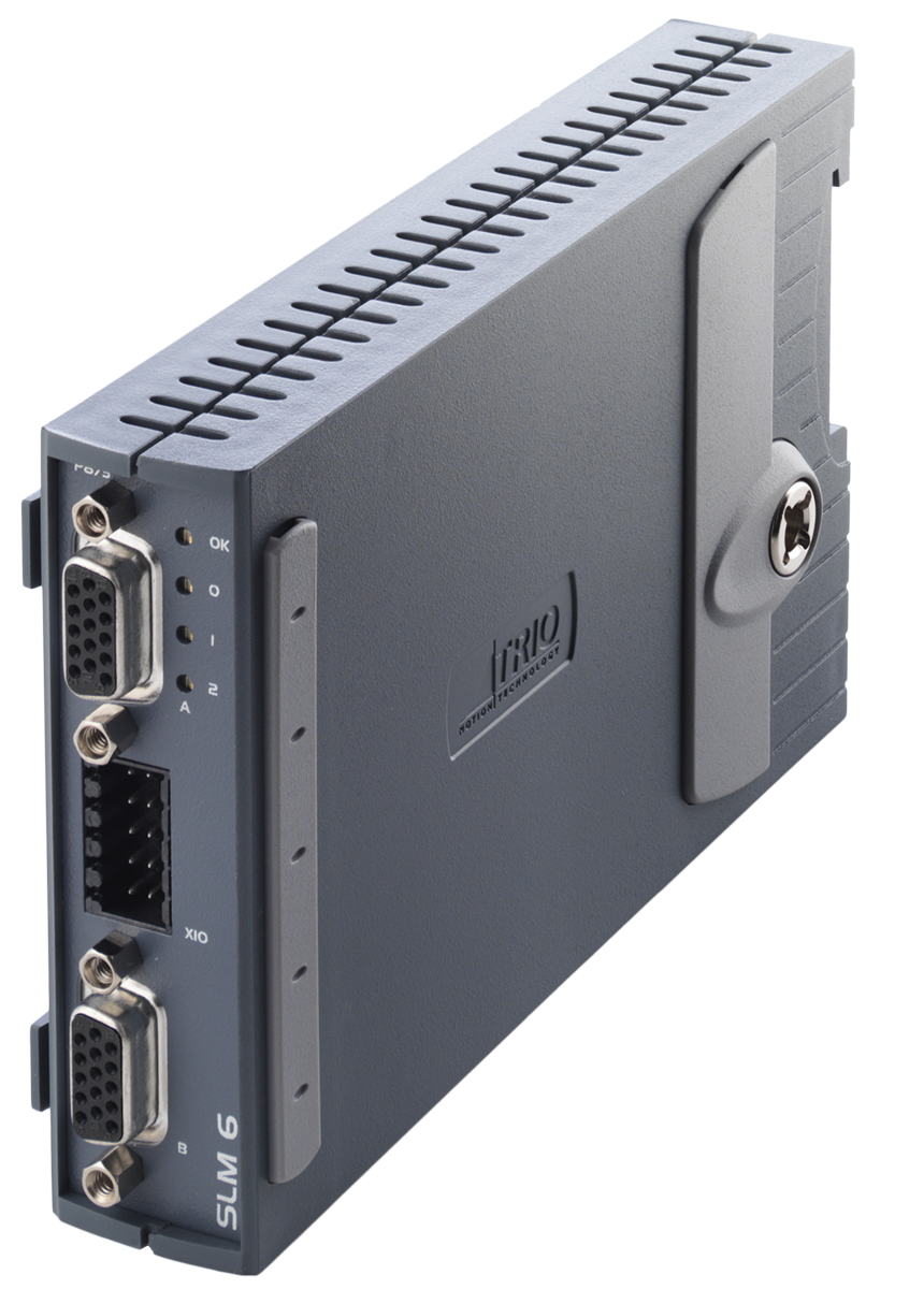
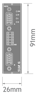
SLM Module
P873
SLM (Speed Loop Motor) Technology forms the basis for Control Techniques' range of Precision Servo Amplifiers, based on a digital high-speed communication system that links the controller, motor and amplifier.
Features
- Max provides a single high performance SLM axis for motors of up to 20Nm
- MultiAx integrates three high performance SLM axes in one module for servo motors of up to 23Nm
- Unidrive SP utilises a Control Techniques click-in SLM option module to provide a single high performance SLM axis for use with higher power and higher speed motors
The feedback resolution provides over 8 million counts per revolution and the speed, current and position loops are updated every 125us to provide optimum performance.
| Network | SLM |
| Network Speed | SLM Standard |
| Topology | Star |
| Max Slaves per Interface Ring | 6 |
| Max Interfaces per MC664 | 7 |
| Max Axes per MC664 | 42 |
| Cable | RS485 |
| Bus to MC664 | 32 Bit |
| Registration Inputs | 6 x 24V Inputs |
| Add Registration Capability | Y |
| Optically Isolated registration Inputs | Y |
| Map Any I/O to Any Axis | Y |
| RoHs | Compliant |
| Guides | |
|---|---|
| Data Sheet | |
| Quick Start Guide | Simple set up guide |
| Flex Axis Splitter Cable (P381) | Simple Pin-Out guide |
| Manuals | |
|---|---|
| The Technical Reference Manual can be downloaded in full or as separate sections. All in PDF format. | |
| MC664 Expansion Modules (Chapter 3).pdf | |
| Certificates | |
|---|---|
| UL Listing | Please insert E238097 UL File Number in the search box. |
| CAD Data | |
|---|---|
| Drawings are available in the following formats: DXF, IGES, DWG, STEP and SolidWorks. These files are included in the Zip file below. | |
| Download Zip file | |
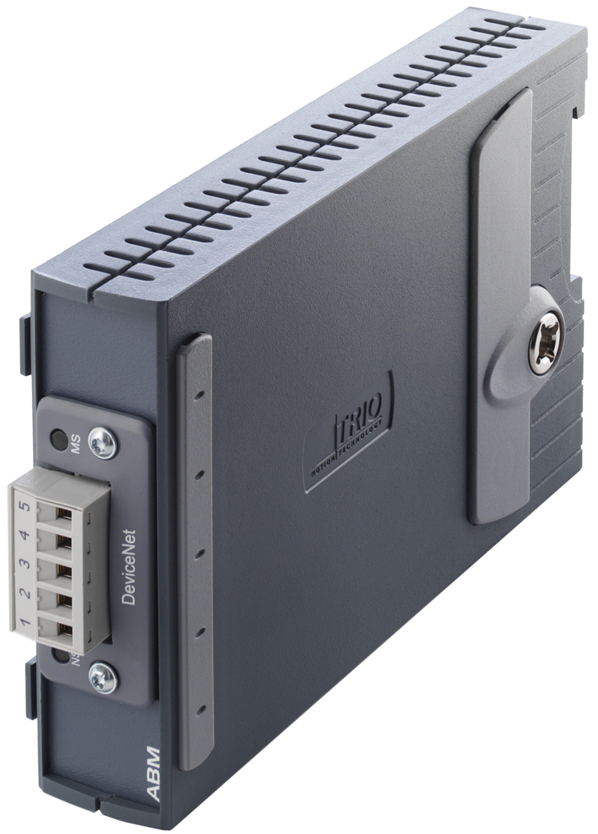
Anybus CC Module
P875
In today's manufacturing environment, open communications is an important aspect to any control system. This module adds support for the Anybus CompactCom device modules.
Features
- Supports Anybus CC M30 series
- Major FieldBus protocols supported
- RoHs Compliant
Anybus-CC is the latest range of cost optimized plug-in modules supporting all major Fieldbus and Ethernet networks. With its innovative design and versatile functionality, the Anybus-CC provides optimal flexibility for OEM manufacturers.
CompactCom Module Options | |
Profibus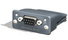
|
Modbus-TCP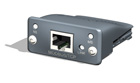 Contact Trio for availability. |
DeviceNet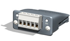
|
Profinet-IO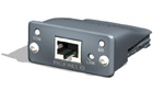
|
Profinet
I/O 2-Port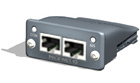
|
EtherCAT
Slave Contact Trio for availability. |
EtherNet/IP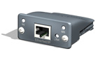 Contact Trio for availibility. |
RS-485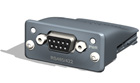
|
Bluetooth
|
RS-232
|
| Guides | |
|---|---|
| Data Sheet | |
| Quick Start Guide | Simple set up guide |
| Flex Axis Splitter Cable (P381) | Simple Pin-Out guide |
| Manuals | |
|---|---|
| The Technical Reference Manual can be downloaded in full or as separate sections. All in PDF format. | |
| MC664 Expansion Modules (Chapter 3).pdf | |
| Certificates | |
|---|---|
| EC Declaration | |
| UL Listing | Please insert E238097 UL File Number in the search box. |
| CAD Data | |
|---|---|
| Drawings are available in the following formats: DXF, IGES, DWG, STEP and SolidWorks. These files are included in the Zip file below. | |
| Download Zip file | |
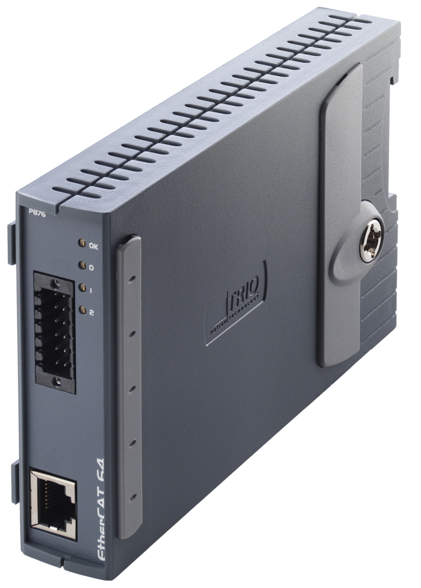
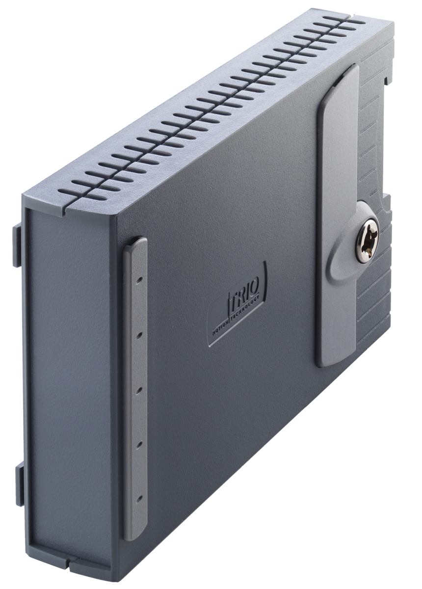
EtherCAT Module
P876
EtherCAT sets new standards for real-time performance and topology flexibility, whilst meeting or under cutting other fieldbus cost levels.
Features
- 8 Registration inputs repeatable to 100nS per module
- Drive parameters setup from the controller
- Position Set point update 0.125mS
- RJ45 Connector
- 4 LED status indicators
P876 EtherCAT master module enables the MC664 Motion Coordinator to enter a very exclusive club offering an independent, standalone EtherCAT master for motion control; this arrangement enables up to 64 axes of any manufacturers' EtherCAT-compatible drives and motors - or other devices - to be controlled. The module comes with 2 axes enabled. Further axes can be enabled with ‘Feature Enable Codes’.
Every axis can be programmed to move using linear, circular or helical interpolation, electronic cams and gearboxes. Features include support for merging multiple moves that are typically generated by CAD/CAM software, plus support is provided for continuously rotating machinery. EtherCAT also offers the major advantage of high-precision device synchronisation.
| Network | EtherCAT |
| Network Speed | 100Mbps |
| Topology | Chain |
| Max Slaves per Interface | 64 |
| Max Interfaces per MC664 | 7 |
| Max Axes per MC664 | 64 |
| Cable | STP Cat 5-e or Better |
| Bus to MC664 | 32 Bit |
| Registration Inputs | 8 x 24V Inputs |
| Optically Isolated registration Inputs | Y |
| Map Any I/O to Any Axis | Y |
| Axis Feature Enable Codes | P914 |
| RoHs | Compliant |

| Guides | |
|---|---|
| Data Sheet | |
| Quick Start Guide | Simple set up guide |
| Flex Axis Splitter Cable (P381) | Simple Pin-Out guide |
| Manuals | |
|---|---|
| The Technical Reference Manual can be downloaded in full or as separate sections. All in PDF format. | |
| MC664 Expansion Modules (Chapter 3).pdf | |
| Certificates | |
|---|---|
| UL Listing | Please insert E238097 UL File Number in the search box. |
| CAD Data | |
|---|---|
| Drawings are available in the following formats: DXF, IGES, DWG, STEP and SolidWorks. These files are included in the Zip file below. | |
| Download Zip file | |
 Specification Specification |
|
|---|---|
| Speed | 100Mbps |
| Physical Layer | 100BASE-TX full duplex (IEEE 802.3) |
| Cable | Shielded Twisted Pair (TIA/EIA-568B CAT5e) |
| Topology | Line, tree or star (1) |
| Isolation | Pulse transformer with common-mode choke |
| Connector | RJ45 |
| Cable Length | 100m max between nodes |
| Cyclic period | 125µsec (Flex-X Nano, Flex-6 Nano, MC6N) 250µsec (MC664-X) 500µsec, 1000µsec, 2000µsec or 4000µsec (MC664, Flex-6 Nano, Flex-X Nano, MC6N) |
| Synchronisation | Distributed Clocks technology. Jitter < 1 µsec |
| Protocol | CoE, SoE (2) |
| Number of Axes | 32 (MC4N) 64 (MC464+P876) 128 (MC664-X) 64 (PC-MCAT-64, PC-MCAT-2) 64 (Flex-X Nano, Flex-6 Nano, MC6N) |
| Number of Nodes | 128 slave nodes maximum |
| Motion modes | Cyclic Synchronous Position, Cyclic Synchronous Velocity, Cyclic Synchronous Torque |
| Parameter transfer | CoE Object read/write. SoE IDN read/write |
| Input/Output | Up to 1024 input bits and 1024 output bits |
| (1) Tree and star require the use of EtherCAT switches. (2) CanOpen application protocol over EtherCAT. (CoE) Servo drive profile according to IEC 61491 over EtherCAT. (SoE) |
|
Blanking Module
P878
Used to ensure the system is 'tied' together mechanically. There is no communication bus connection, but the P878 Blanking Module is required for the earth connection when using extra Expansion Modules.
| Guides | |
|---|---|
| Data Sheet | |
| Quick Start Guide | Simple set up guide |
| Flex Axis Splitter Cable (P381) | Simple Pin-Out guide |
| Manuals | |
|---|---|
| The Technical Reference Manual can be downloaded in full or as separate sections. All in PDF format. | |
| MC664 Expansion Modules (Chapter 3).pdf | |
| Certificates | |
|---|---|
| EC Declaration | |
| UL Listing | Please insert E238097 UL File Number in the search box. |
| CAD Data | |
|---|---|
| Drawings are available in the following formats: DXF, IGES, DWG, STEP and SolidWorks. These files are included in the Zip file below. | |
| Download Zip file | |
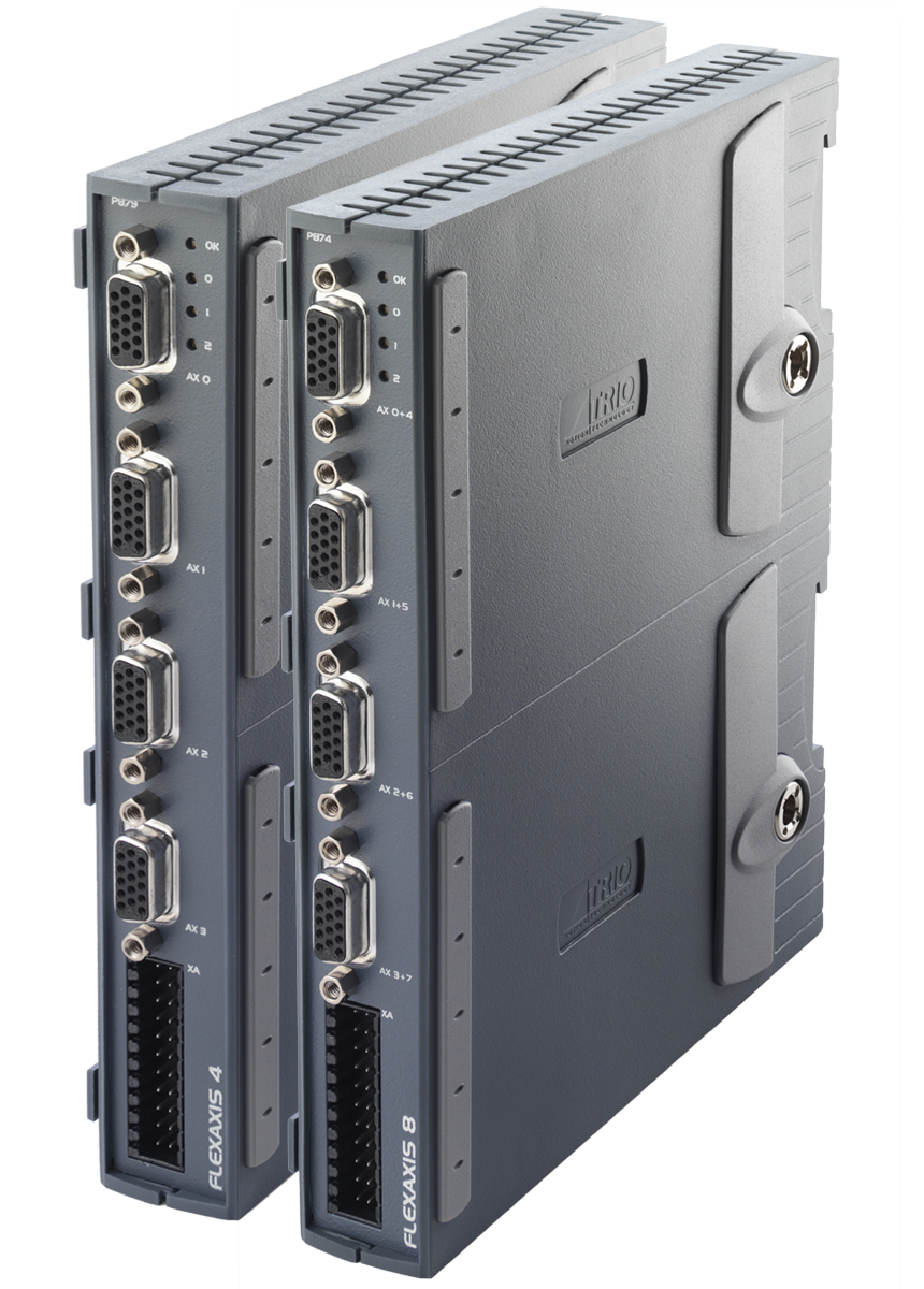
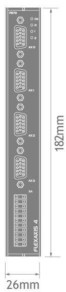
FlexAxis Module
P874 | P879 | P881 | P883
For use with Stepper, Analogue Servo & Piezo motors with support available for SSI / EnDat / Tamagawa and BiSS Absolute encoders.
Features
- Up to 24 axes per MC664 (X)
- Flexible dual registration inputs on all axes (max 8 / unit)
- Up to 3 modules per MC664 (X)
- Available in 4 and 8 axis configuration
Standard FlexAxis Interface modules are available in 4 axis (P879) and 8 axis (P874) versions. An 8 axis SSI absolute encoder version (P881) and a BiSS absolute encoder version (P883) is available as a special order.
| P874 | P879 | P881 | P883 | ||
|---|---|---|---|---|---|
| Configuration Core = Pulse/direction and Incremental Encoder functionality. Extended = core + Absolute + Servo functionality AS = Analogue 'closed loop' Servo using built-in ±10V analogue output. |
Axis 0 | Core+AS | Core+AS | Core+AS+SSI | Core+AS+BiSS |
| Axis 1 | Core+AS | Core+AS | Core+AS+SSI | Core+AS+BiSS | |
| Axis 2 | Core+AS | Extended+AS | Core+AS+SSI | Core+AS+BiSS | |
| Axis 3 | Core+AS | Extended+AS | Core+AS+SSI | Core+AS+BiSS | |
| Axis 4 | Extended+AS | Core+AS+SSI | |||
| Axis 5 | Extended+AS | Core+AS+SSI | |||
| Axis 6 | Extended+AS | Core+AS+SSI | |||
| Axis 7 | Extended+AS | Core+AS+SSI | |||
| Max servo or stepper axes | 8 | 4 | 8 | 4 | |
| Max encoder inputs (6MHz edge rate) - Opto isolated RS422 line receiver | 8 | 4 | 8 | 4 | |
| Max pulse/dir stepper or enc outputs (2MHz) - Opto isolated RS422 line drive | 8 | 4 | 8 | 4 | |
| Number of 16 Bit DAC Outputs | 8 | 4 | 8 | 4 | |
| Max SSI Absolute Encoder Axes | 4 | 2 | 8 | 0 | |
| Max EnDat Absolute Encoder Axes | 4 | 2 | 0 | 0 | |
| Max Tamagawa Absolute Encoder Axes | 4 | 2 | 0 | 0 | |
| Max BiSS Absolute Encoder Axes | 0 | 0 | 0 | 4 | |
| RoHs | Compliant | Compliant | Compliant | Compliant |
Key
Axis Configuration Key
| Core functionality | |||
|---|---|---|---|
CORE AXES – can be configured in software as pulse and direction outputs with stepper or servo drives. They can also be configured for incremental encoder feedback. Core functionality is a set of ATYPEs (Axis TYPEs) that are available on all controllers. They are based on pulse outputs and incremental encoder feedback. |
|||
| ATYPE | Description | ||
| 43 | Pulse and direction output with enable output | ||
| 45 | Quadrature encoder output with enable output | ||
| 63 | Pulse and direction output with Z input | ||
| 64 | Quadrature encoder output with Z input | ||
| 76 | Incremental encoder with Z input | ||
| 78 | Pulse and direction with VFF_GAIN and enable output 1 | ||
| Extended functionality | |||
|---|---|---|---|
EXTENDED AXES – in addition to the Core functionality these axes can also be configured for absolute encoders and closed loop servos (requires voltage output). Only axes marked as AS have an analogue output and can be used for closed loop control. |
|||
| ATYPE | Description | ||
| 30 | Analogue feedback Servo | ||
| 44 | Incremental encoder Servo with Z input | ||
| 46 | Tamagawa absolute Servo | ||
| 47 | Endat absolute Servo | ||
| 48 | SSI absolute Servo | ||
| 60 | Pulse and direction feedback Servo with Z input | ||
| 77 | Incremental encoder Servo with enable output | ||
| 92 | Biss absolute servo | ||
| Guides | |
|---|---|
| Data Sheet | |
| Quick Start Guide | Simple set up guide |
| Flex Axis Splitter Cable (P381) | Simple Pin-Out guide |
| Manuals | |
|---|---|
| The Technical Reference Manual can be downloaded in full or as separate sections. All in PDF format. | |
| MC664 Expansion Modules (Chapter 3).pdf | |
| Certificates | |
|---|---|
| EC Declaration | |
| UL Listing | Please insert E238097 UL File Number in the search box. |
| CAD Data | |
|---|---|
| Drawings are available in the following formats: DXF, IGES, DWG, STEP and SolidWorks. These files are included in the Zip file below. | |
| Download Zip file | |
